
1 / 5
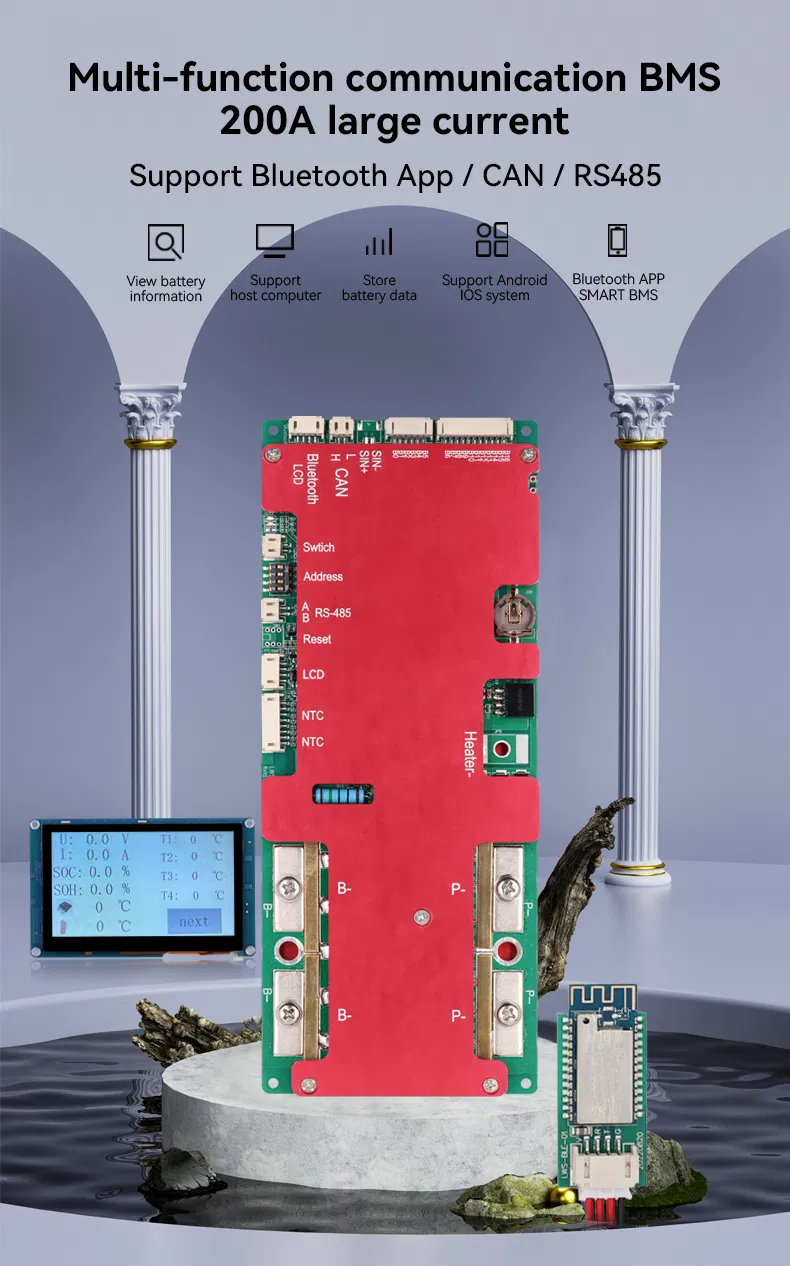
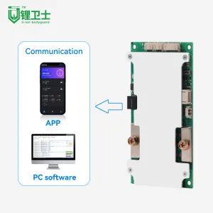
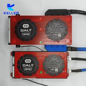
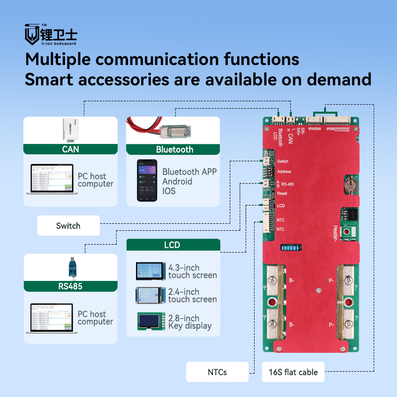
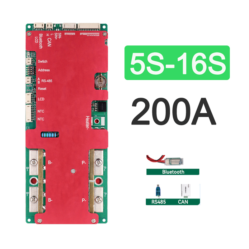
This Smart 16S 200A BMS is a sophisticated battery management system designed for monitoring and protecting a 16-cell Lifepo4 battery pack with a nominal voltage of 51.2V. It ensures stable load performance with continuous current support up to 100A-200A.
| Mode | LWS-16S200A-809V3 |
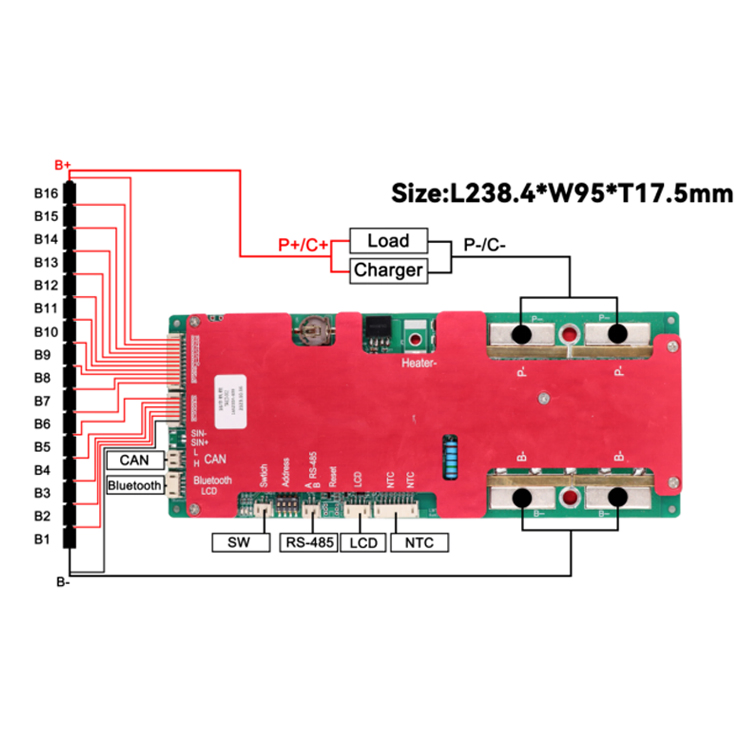
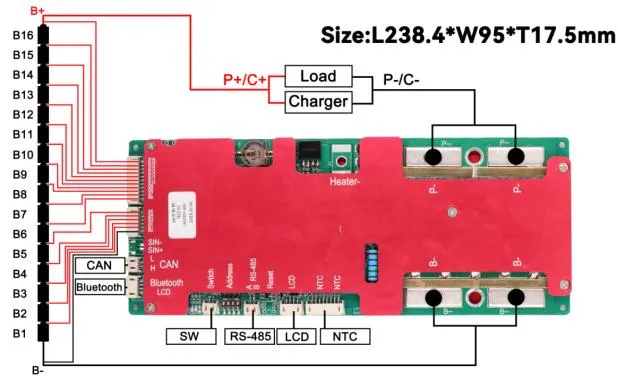
| PCM Size | L238.4*W95*T17.5 mm |
| Battery Series | 16S Available |
| Working Current | 200A Available |
| Cell Type | Li-ion (51.2V) / LiFePO4 (59.2V) |
| Category | Test Item | Criterion |
|---|---|---|
| Voltage | Charging voltage | DC: 58.4V CC/CV |
| Balance voltage for single cell | 3.2±0.025V | |
| Current | Balance current for single cell | 75±20mA |
| Current consumption | ≤ 50μA | |
| MAX Continuous current | ≤ 100A | |
| Over Charge | Detection voltage | 3.75±0.025V |
| Release voltage | 3.5±0.05V | |
| Over Discharge | Detection voltage | 2.50±0.05V |
| Release voltage | 2.8±0.10V | |
| Short Circuit | Protection current | ≈1000A (Auto Recovery) |
| Temperature | Operating Range | -20 ~ +60ºC |
Step 1: Connect the B- to the battery negative terminal (weld the stub first). Remove cables from BMS before connecting.
Step 2: Start wiring from B-. Connect the sideline B1 to the positive of the first battery, B2 to the second, and so on.
Step 3: Test voltage between adjacent lines. Li-ion should be < 4V, LFP should be < 3.5V. If correct, insert the line.
Step 4: Connect the negative terminal of charger/load to P-/C-. Use bold cables for high current paths.