1 / 5
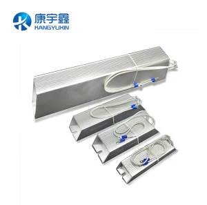
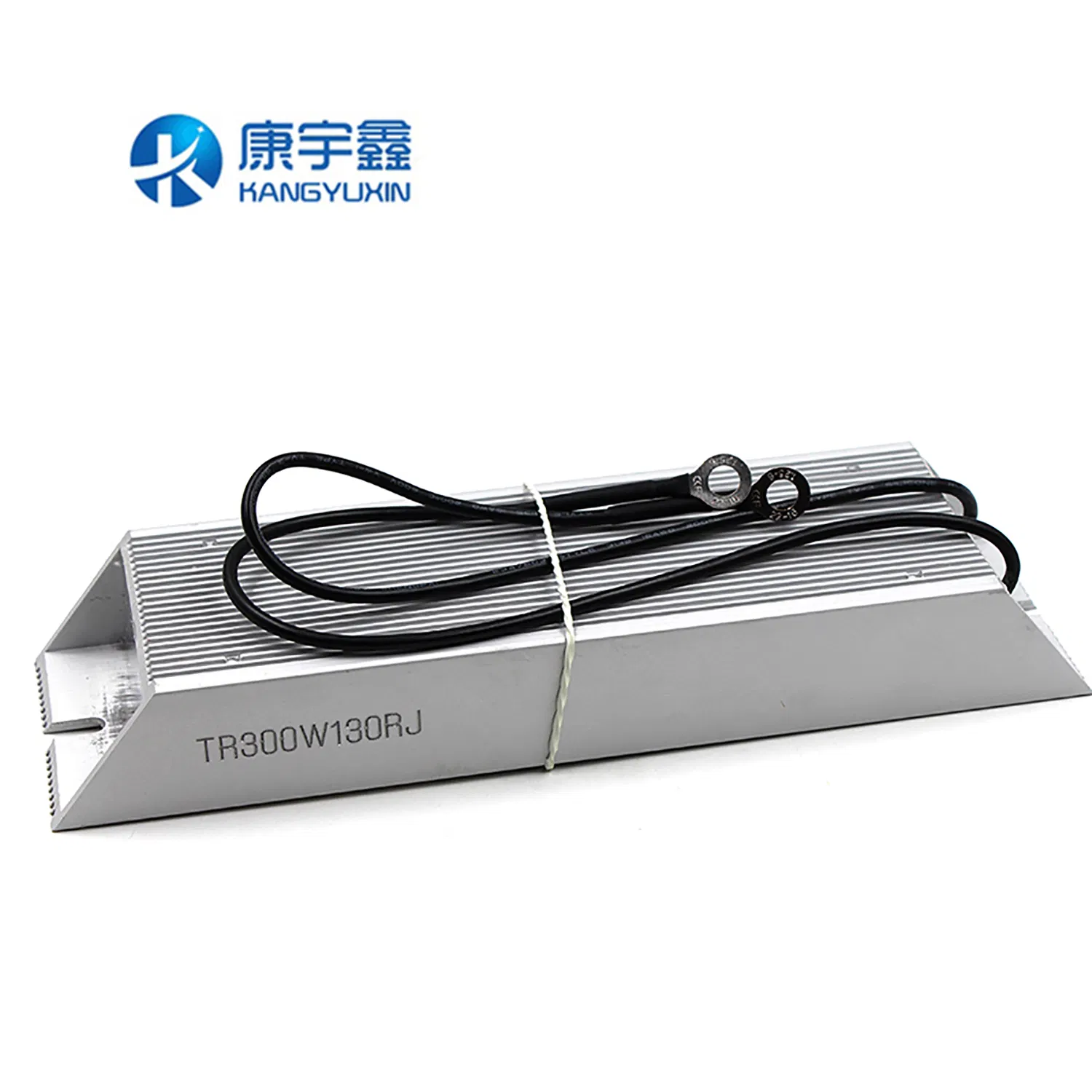
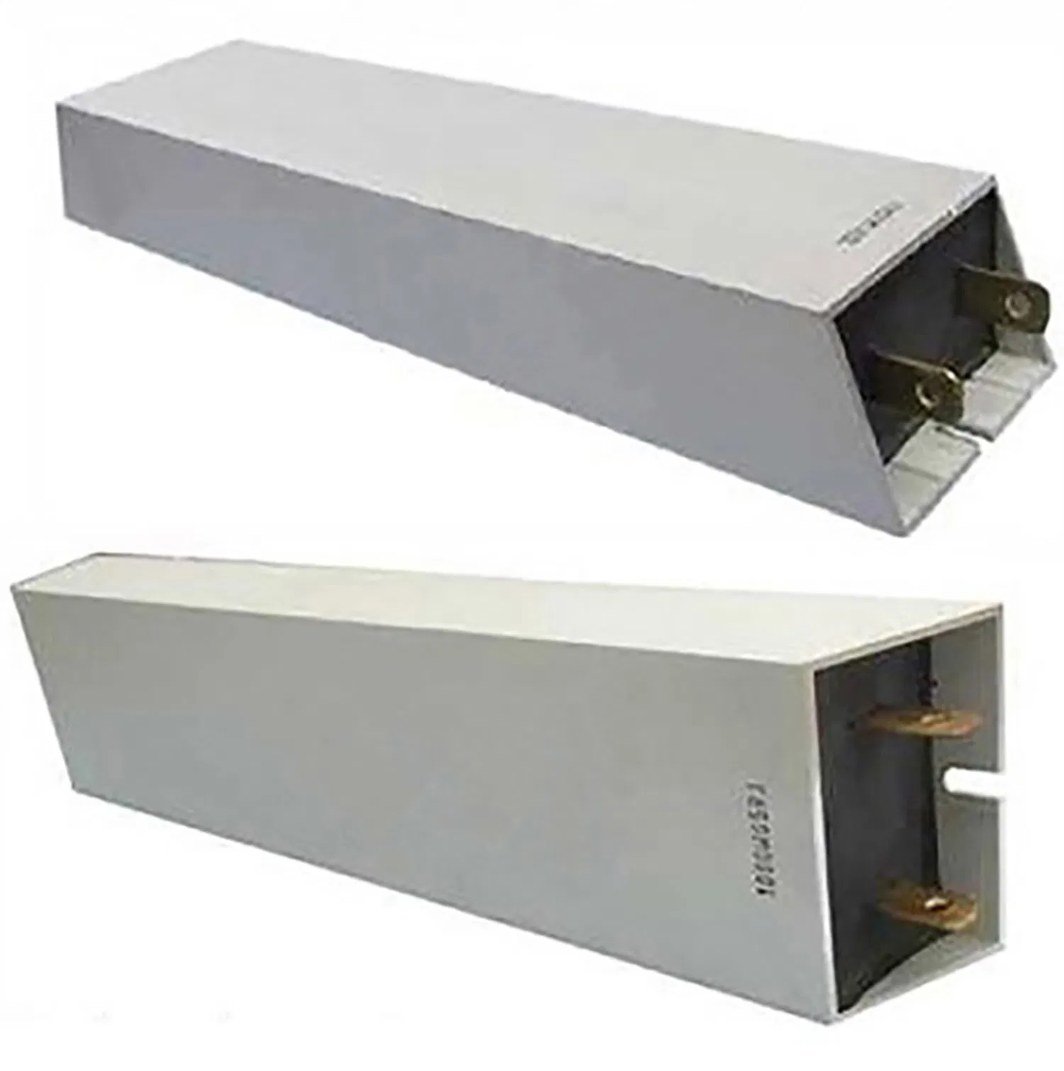
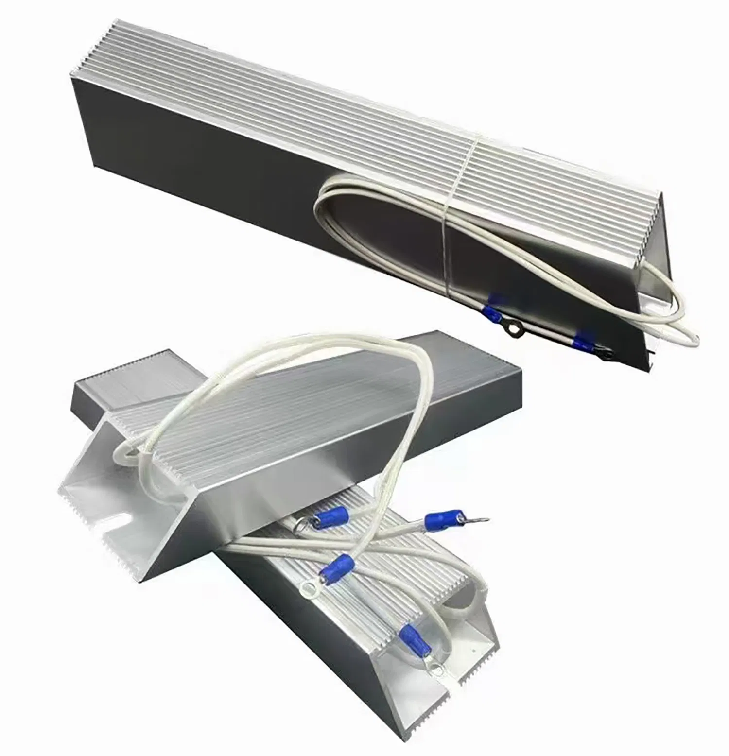
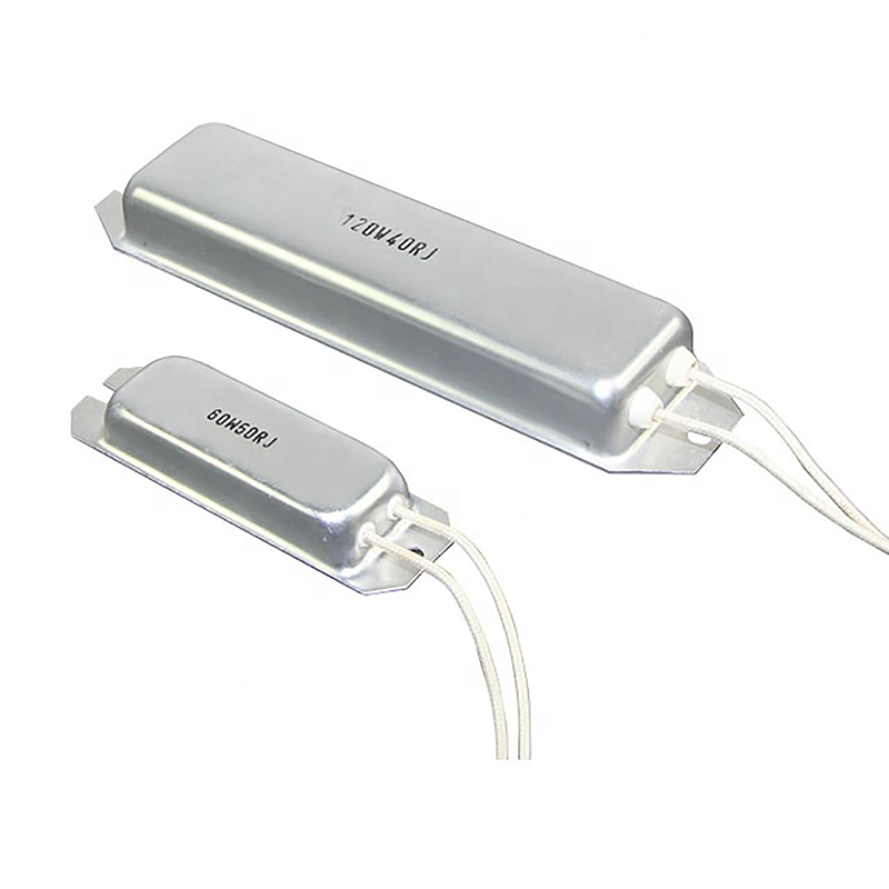
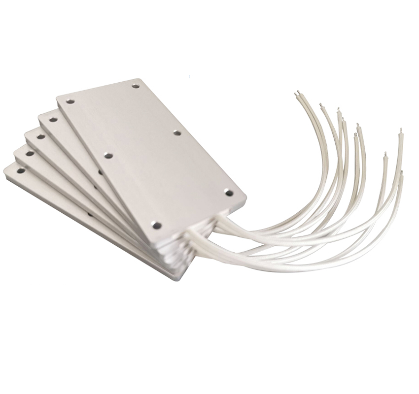
Our resistor series, including ASZ (trapezium shape), ASC (ship shape), and ASCB (ultrathin shape), offers more than 20 mold types to ensure the resistors suit various environmental installations and applications.
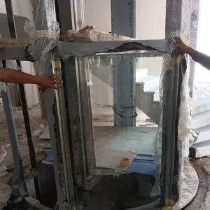
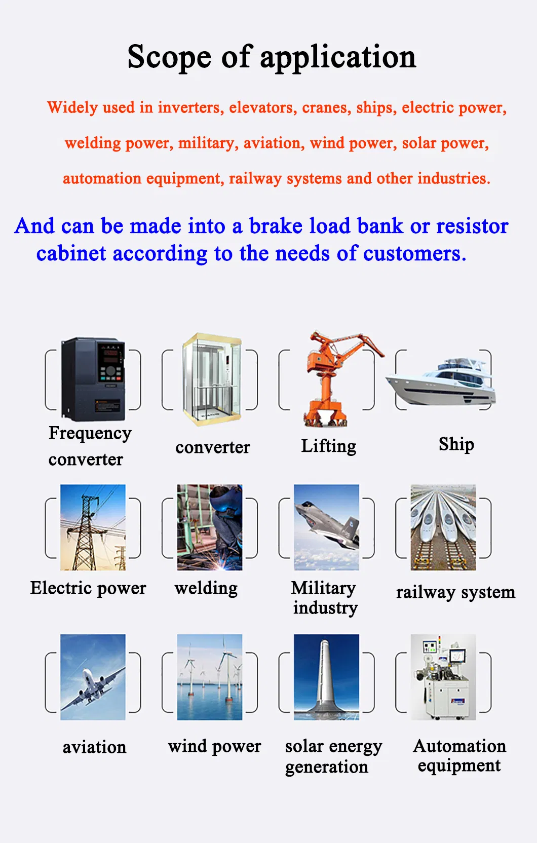
The product is easy to utilize and install, and suitable for a wide range of applications. Applications include industrial machinery, load testing, electric power distribution, instruments, and automated control installations.
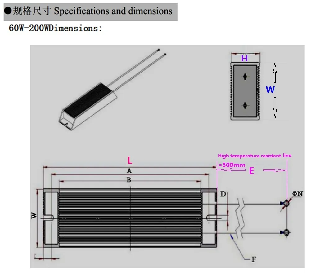
| Power (W) | Bottom length (L) | Width (W) | High (H) | Face length (B) | Pitch (A) | Slot width (D) | Line length (E) | Terminal diameter (N) |
|---|---|---|---|---|---|---|---|---|
| 60 | 100 | 40 | 20 | 75 | 80 | 5.5 | 300 | 4 |
| 80 | 110 | 40 | 20 | 85 | 90 | 5.5 | 300 | 4 |
| 100 | 115 | 40 | 20 | 90 | 95 | 5.5 | 300 | 4 |
| 120 | 165 | 40 | 20 | 140 | 145 | 5.5 | 300 | 4 |
| 150 | 185 | 40 | 20 | 160 | 165 | 5.5 | 300 | 4 |
| 200 | 215 | 40 | 20 | 190 | 195 | 5.5 | 300 | 4 |
| The power and dimension can be customized for customers. | ||||||||
| Power (W) | Bottom length (L) | Width (W) | High (H) | Face length (B) | Pitch (A) | Slot width (D) | Line length (E) | Terminal diameter (N) |
|---|---|---|---|---|---|---|---|---|
| 200 | 165 | 60 | 30 | 125 | 145 | 5.5 | 300 | M4 |
| 300 | 215 | 60 | 30 | 175 | 195 | 5.5 | 300 | M4 |
| 400 | 265 | 60 | 30 | 225 | 245 | 5.5 | 300 | M4 |
| 500 | 285 | 60 | 30 | 245 | 265 | 5.5 | 300 | M4 |
| 600 | 300 | 60 | 30 | 260 | 280 | 5.5 | 300 | M4 |
| 800 | 330 | 60 | 30 | 290 | 310 | 5.5 | 300 | M4 |
| 1000 | 330 | 60 | 30 | 345 | 365 | 5.5 | 400 | M4 |
| The power and dimension can be customized for customers. | ||||||||
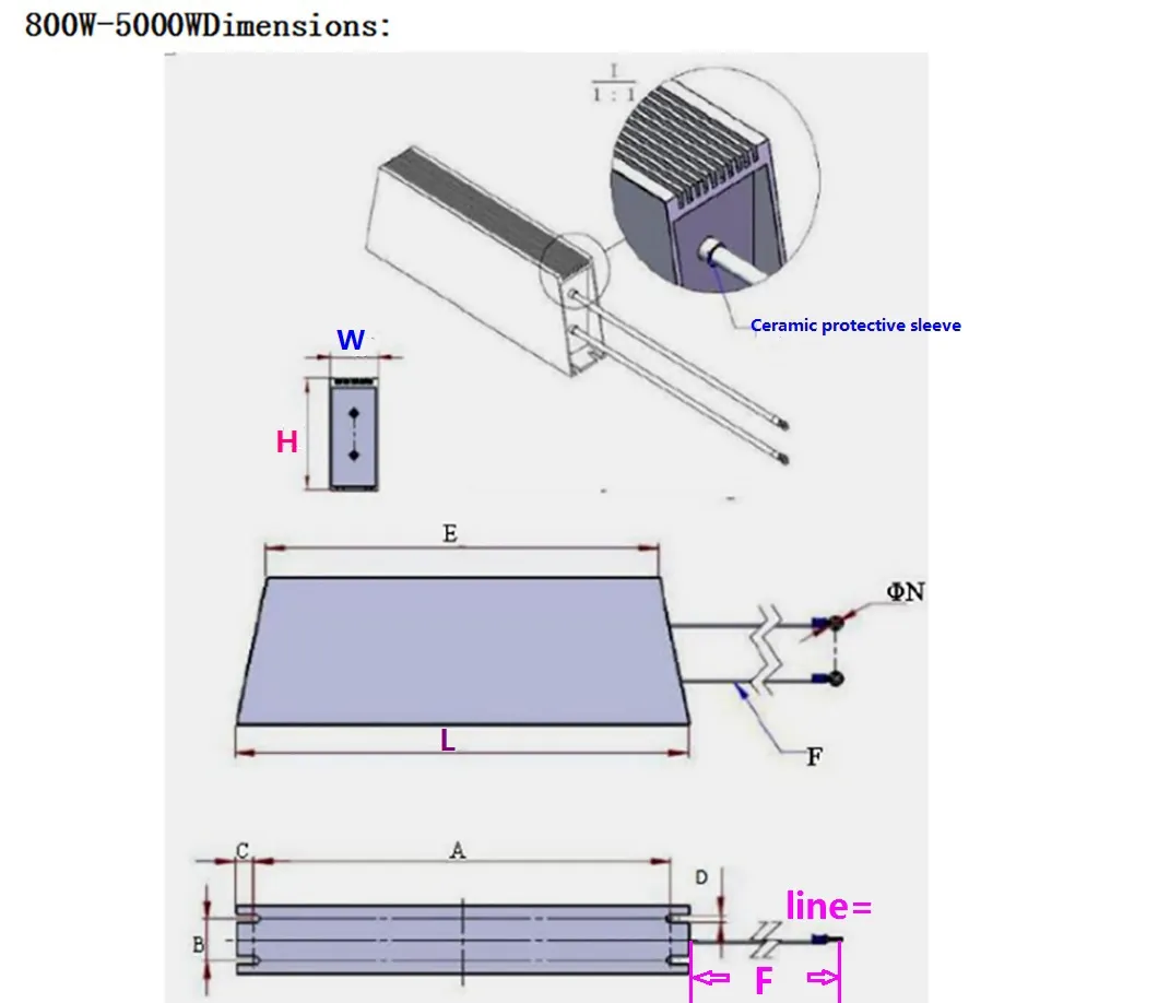
| Power (W) | Bottom length (L) | High (H) | Width (W) | Face length (E) | Pitch (A) | Slot distance (B) | Slot length (C) | Slot width (D) | Line length (F) | Terminal diameter (N) |
|---|---|---|---|---|---|---|---|---|---|---|
| 800 | 210 | 107 | 50 | 170 | 190 | 30 | 10 | 6.5 | 300 | 6 |
| 1000 | 300 | 107 | 50 | 260 | 280 | 30 | 10 | 6.5 | 350 | 6 |
| 1500 | 400 | 107 | 50 | 360 | 380 | 30 | 10 | 6.5 | 450 | 6 |
| 2000 | 450 | 107 | 50 | 410 | 430 | 30 | 10 | 6.5 | 500 | 6 |
| 2500 | 485 | 107 | 50 | 445 | 465 | 30 | 10 | 6.5 | 535 | 6 |
| 3000 | 550 | 107 | 50 | 510 | 530 | 30 | 10 | 6.5 | 600 | 6 |
| 4000 | 650 | 107 | 50 | 610 | 630 | 30 | 10 | 6.5 | 700 | 6 |
| 5000 | 750 | 107 | 50 | 710 | 730 | 30 | 10 | 6.5 | 800 | 6 |
| The power and dimension can be customized for customers. | ||||||||||
| Test item | Test condition | Specifications |
|---|---|---|
| Resistance tolerance | JIS-C-5202 5-1 | Resistance Nominal Tolerance 1≤R 1>R ±5%(J), ±10%(K) |
| Temperature coefficient | JIS-C-5202 5-2 | ±250PPM/ºC Max |
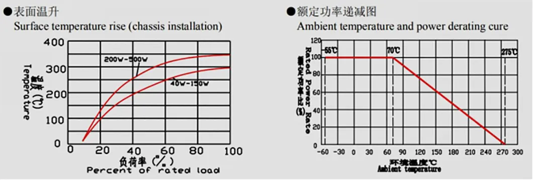
| Power rating load | JIS-C-5202 5-4 40ºC, power rating 1H | △R≤±(1%+0.1Ω), Surface temperature up ≤350ºC MAX |
| Short-term overload | JIS-C-5202 5-5, 500% rated power 5 seconds | Free of appearance or structural irregularity, △R≤±(2%+0.1Ω) |
| Insulation resistance | JIS-C-5202 5-6 1000V DC | 100 MΩ Min |
| Dielectric withstanding voltage | JIS-C-5202 5-7, 2000V DC 1 minute | Free of appearance or structural irregularity, △R/R≤±(0.1%+0.05Ω) |
| Terminal strength | JIS-C-5202 6-1 ASZ 8kg 30s ASCB / ASC 5kg 10s | Free of appearance or structural irregularity |
| Resistor strength | JIS-C-5202 6-2 ASZ 30kg 30s ASCB / ASC 10kg 10s | Free of appearance or structural irregularity |
| Vibration | JIS-C-5202 6-3 1.5mm, 10-50-10Hz/min X-Y-Z 2 hours each | Free of appearance or structural irregularity, Surface coating crack △R≤±(1%+0.05Ω) |
| Thermal shock | JIS-C-5202 7-3 Room temp 30 minutes, ON-55ºC 15 minutes OFF | Resistor free of structural irregularity, crack of silicon cement surface △R≤±(2%+0.1Ω) |
| Humidity | JIS-C-5202 7-5, 40ºC 90%RH 240H | Free of appearance or structural irregularity, Surface coating crack ΔR/R≤±(3%+0.1Ω) |
| Load life | JIS-C-5202 7-10, 90Min ON - 30Minutes OFF 500H | Free of appearance or structural irregularity, Discoloration of marking △R≤±(3%+0.1Ω) |

Power supplies, elevators, inverters, automotive systems, generators, shipping, power grid distribution, and more.
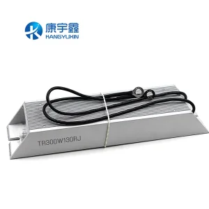
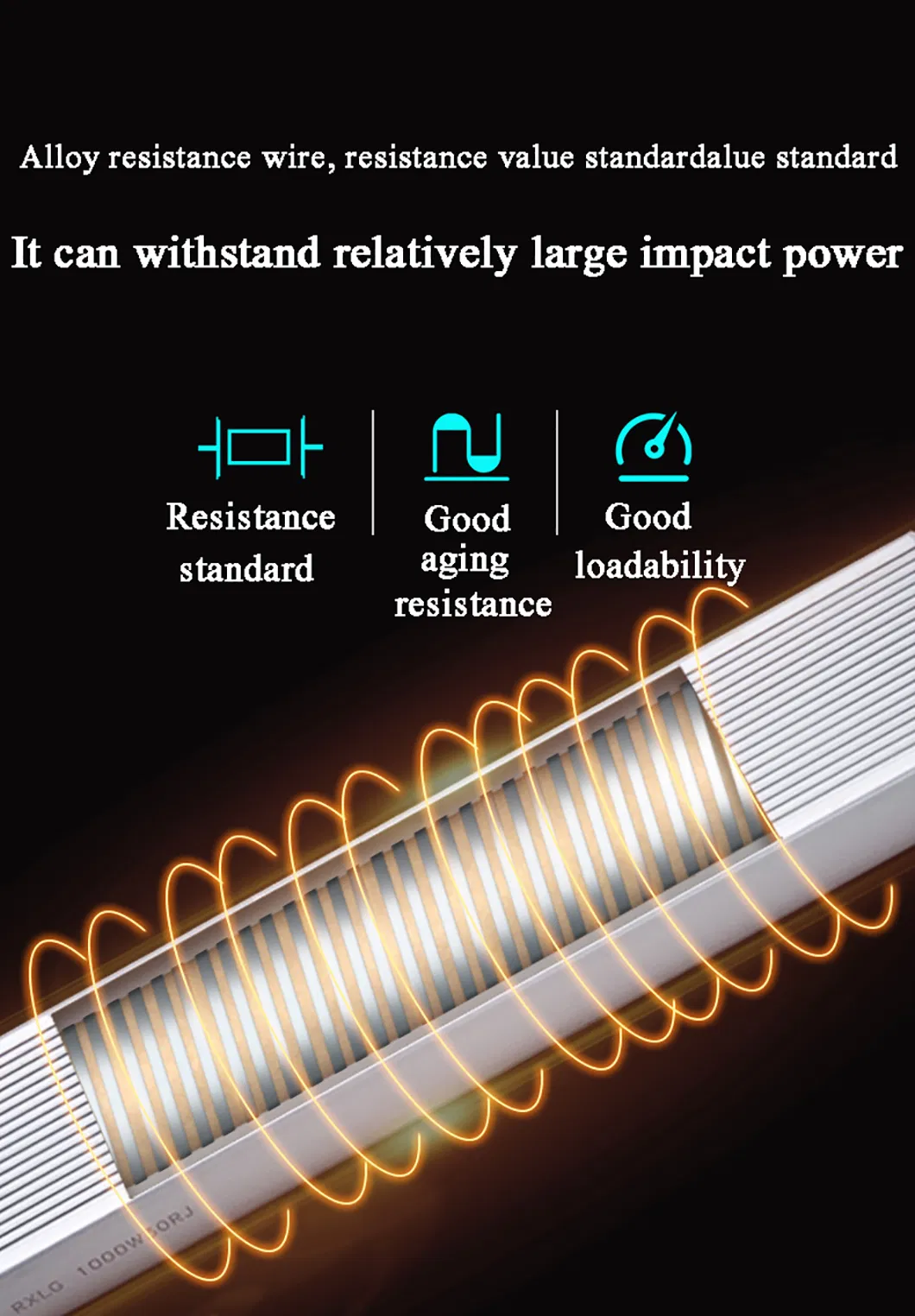
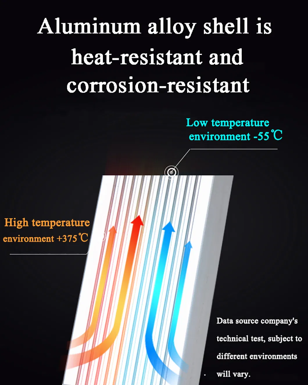
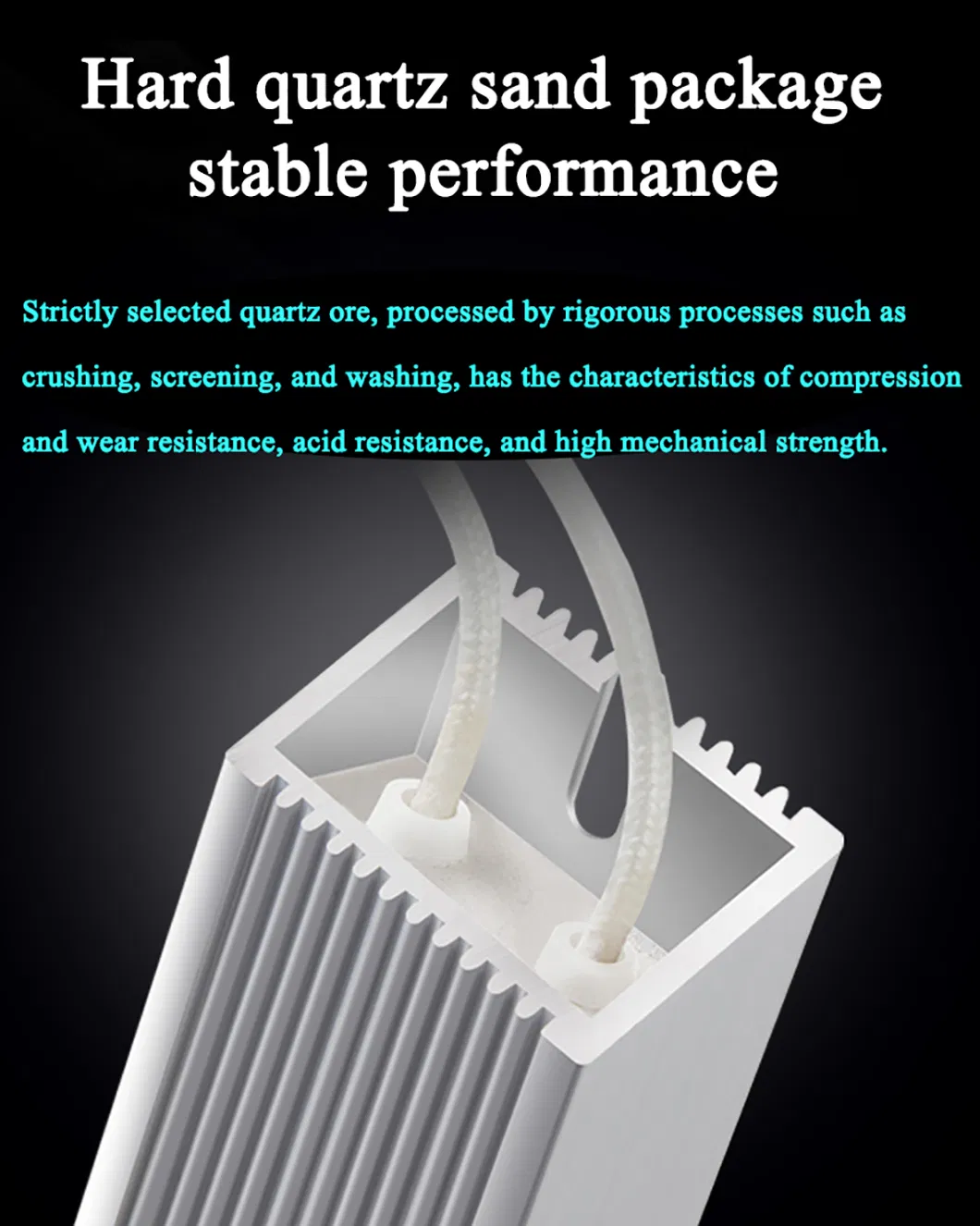
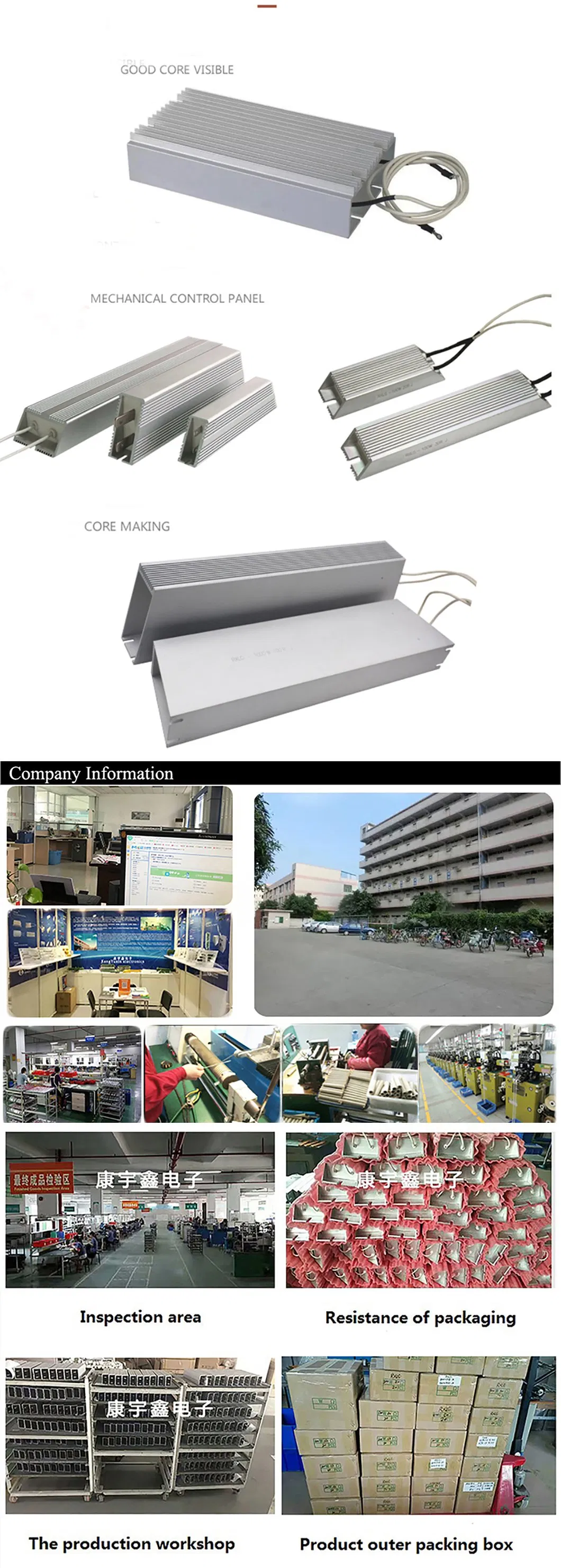
Adopts high-temperature resistant materials as the matrix. Potting with high-insulation, non-combustible filler ensures a tight bond between the resistance wire and the metal outer shell, delivering higher durability than standard aluminum shells:
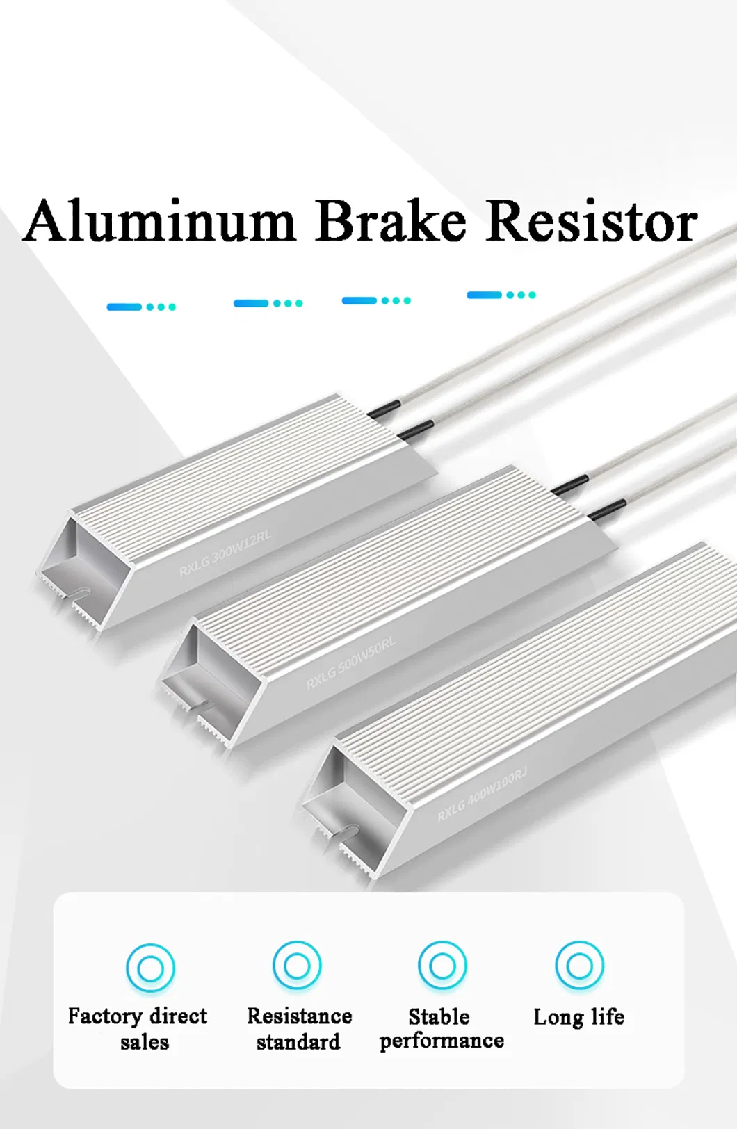
The RXLG brake resistor is widely used in elevator systems, frequency inverters, machine tools, wind power facilities, ships, power distribution grids, cars, generators, and automated control systems.
These resistors feature anodized aluminum shells filled with specialized non-flammable cement. This ensures efficient thermal conductivity, high vibration resistance, dust protection, and reliable operation in harsh environments.
Yes. The power ratings, dimensions, values, and wiring configurations can be specifically customized according to customer needs for non-standard technical requirements.
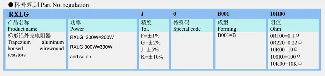
We offer standard rated powers from 50W to 6000W, and resistance values from 0.1Ω to 100KΩ with tolerance options of ±1%, ±2%, ±5%, and ±10%.
Our aluminum brake resistors are manufactured in strict compliance with the international RoHS standards and LEAD-FREE environmental criteria.
The typical production and delivery timeframe for these resistors ranges from 5 to 7 days, depending on the custom specifications required.