Understanding how do electric vehicle components work together begins with the energy path. Electricity leaves the high-voltage battery pack and reaches the inverter through carefully insulated cables. The battery stores direct current, while the inverter converts it into controlled alternating current for the traction motor. That motor then turns electrical energy into wheel movement through a reduction gear and differential.
The process is coordinated, not isolated. Sensors measure speed, temperature, voltage, and accelerator position several times per second. A vehicle control unit interprets this information and adjusts torque requests. The battery management system protects individual cells from excessive heat, charging, or discharge. Cooling plates and circulating coolant help maintain a safer operating range during highway travel or steep climbs. Small details matter here.
When the driver releases the accelerator, the motor can work as a generator. This regenerative braking sends some kinetic energy back to the battery. Friction brakes still provide dependable stopping power, especially during emergencies or low-speed conditions. Charging equipment adds another layer, converting grid electricity into a form the battery can accept safely. Engineers validate these interactions through testing, simulations, and real-world driving data.
The picture is not perfectly simple. Different models use varied motor designs, battery chemistries, software strategies, and thermal layouts. Some explanations also make electric drivetrains sound more automatic than they really are. This guide examines the connections carefully, using practical examples and established engineering principles. It aims to clarify the system without hiding its limitations, trade-offs, or areas that deserve further reflection.
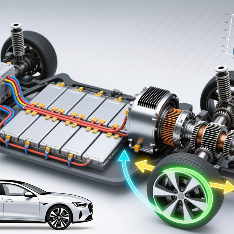
The battery pack is the vehicle’s high-voltage energy reservoir. In a 400–800 V system, cells connect in series to raise voltage. Parallel groups increase capacity and current capability. A battery-management system measures cell voltage, temperature, and state of charge. It also balances cells and opens contactors when faults appear. Small details matter.
The International Energy Agency’s Global EV Outlook 2024 reported more than 14 million electric car sales in 2023. It also estimated global electric-vehicle battery demand at about 750 GWh that year. These figures explain the industry’s focus on efficient energy delivery. At 200 kW, a 400 V pack ideally supplies 500 A. An 800 V pack supplies 250 A. Lower current can reduce cable heating and resistive losses, although insulation and charging hardware become more demanding.
The pack sends direct current through contactors, fuses, and high-voltage cables. An inverter then converts DC into three-phase AC for the traction motor. During regenerative braking, the energy path reverses. The motor becomes a generator, and the inverter returns energy to the pack. Voltage labels can mislead. Actual voltage changes with temperature, charge level, and load. NREL charging-infrastructure studies also show that real charging performance depends on station power, thermal limits, and vehicle communication. The neat diagram is useful, but incomplete. Engineers still need to question every measurement.
Typical engineering characteristics of high-voltage electric vehicle battery packs and the way their main components coordinate energy storage, protection, cooling, and delivery.
| Component or Dimension | Typical Data | How It Works | Relationship With Other Components |
|---|---|---|---|
| Battery System Voltage | Approximately 400–800 V DC nominal system class | The pack combines many electrochemical cells in series to produce a high direct-current voltage. Higher voltage allows the same power to be delivered with lower current. | Works with the inverter, onboard charger, DC fast-charging hardware, contactors, insulation monitoring, and high-voltage cables. |
| Cell Chemistry | Common lithium-ion chemistries, including nickel-manganese-cobalt and lithium-iron-phosphate | The chemistry determines energy density, voltage behavior, thermal characteristics, charge acceptance, cycle life, and usable operating limits. | Influences pack size, thermal-management requirements, battery-management algorithms, and charging limits. |
| Cell Configuration | Series-connected cells for voltage; parallel-connected cells for capacity and current capability | Series connections increase voltage, while parallel connections increase ampere-hour capacity and distribute current across multiple cells. | The configuration determines pack voltage, total energy, maximum current, module layout, and the monitoring points used by the battery-management system. |
| Battery Energy | Approximately 40–120 kWh for many passenger-vehicle applications | Stored energy is approximately calculated as nominal voltage multiplied by ampere-hour capacity. Usable energy is lower than the full electrochemical capacity because protective reserve margins are maintained. | Controls potential driving range and affects vehicle mass, charging time, regenerative-braking capacity, and thermal load. |
| Power Delivery | Power is calculated as voltage multiplied by current; the exact value depends on vehicle design and operating conditions | The pack supplies DC power to the inverter, which converts it into controlled AC power for the traction motor. During regeneration, the power flow is reversed. | The battery-management system limits current according to cell temperature, state of charge, voltage, and requested motor or charging power. |
| Battery Modules | Multiple cells grouped into mechanically and electrically organized modules, or into larger integrated assemblies | Modules simplify cell arrangement, sensing, structural support, service procedures, and thermal interfaces. | Module voltage and temperature data are sent to the battery-management system, while busbars and connectors link modules to the pack electrical circuit. |
| Battery-Management System | Monitors cell voltage, temperature, current, state of charge, and state of health | The system estimates available energy and power, balances cell voltages, detects abnormal conditions, and controls charging and discharging limits. | Communicates with the inverter, charger, vehicle control unit, thermal controller, contactors, and safety systems. |
| State of Charge | Displayed as a percentage; the usable range is intentionally narrower than the cell's absolute voltage range | State-of-charge estimation combines current integration with voltage, temperature, and battery-model data to approximate remaining usable energy. | Determines regenerative-braking availability, charging power, propulsion limits, and the vehicle's remaining-range estimate. |
| Thermal Management | Liquid cooling or heating is commonly used; operating targets are often near normal moderate battery temperatures | A thermal circuit removes heat during driving and fast charging and can add heat in cold conditions to improve performance and charging acceptance. | Coordinates with pumps, valves, heat exchangers, sensors, the cabin climate system, and charging-power controls. |
| High-Voltage Contactors | Electrically controlled switches that connect or isolate the battery from the vehicle's high-voltage bus | Contactors remain open when the vehicle is inactive or a serious fault is detected. A pre-charge circuit limits inrush current before the main connection is closed. | Controlled by the battery-management system and interlocked with insulation monitoring, crash sensing, charging equipment, and the inverter. |
| Pre-Charge Circuit | Resistor and switching path used before full high-voltage connection | Gradually charges the inverter's DC-link capacitors, reducing electrical stress and preventing a large inrush current. | Works with the main contactors and inverter before propulsion power becomes available. |
| DC-Link Interface | High-voltage DC bus connecting the battery to power electronics | Provides a stable electrical path between the battery pack and the inverter or other high-voltage converters. | The inverter draws DC energy for propulsion, while onboard charging and regenerative braking can send controlled energy back toward the battery. |
| Charging Path | AC charging uses an onboard charger; DC fast charging supplies controlled DC directly to the high-voltage battery | Charging power is adjusted according to battery voltage, temperature, state of charge, and charger limits. Charging generally tapers at high state of charge. | The battery-management system communicates allowable voltage and current limits to the charging system and opens the contactors if unsafe conditions occur. |
| Regenerative Braking | The traction motor operates as a generator during deceleration | Vehicle kinetic energy is converted into electrical energy and returned as DC energy to the battery through the inverter. | Available regeneration depends on battery temperature, state of charge, cell voltage, motor limits, tire grip, and friction-brake coordination. |
| Protection and Isolation | Fuses, current sensors, insulation monitoring, crash disconnect logic, and sealed enclosures | These features limit fault current, detect unintended electrical paths, isolate damaged circuits, and reduce electric-shock and thermal-event risks. | Safety responses can command contactor opening, reduce power, disable charging, and notify vehicle control systems. |
| Mechanical Enclosure | Rigid, sealed structure mounted within the vehicle floor or chassis | Protects cells and electrical parts from vibration, moisture, debris, and crash loads while contributing to vehicle structural stiffness. | Supports modules, cooling plates, busbars, service disconnects, pressure-management features, and high-voltage connectors. |
Important: Actual voltage, capacity, power, chemistry, cooling strategy, and usable operating limits vary by vehicle design. Values shown are representative engineering ranges rather than specifications for a particular vehicle.
Cells connect in series to raise voltage. Parallel groups increase capacity and current capability. The pack stores direct current. Small details matter.
At the same power, higher voltage requires less current. A 200 kW load needs about 500 amperes at 400 volts. It needs about 250 amperes at 800 volts. Lower current can reduce cable heating and resistive losses.
It measures cell voltage, temperature, and charge level. It balances cells during operation. When a fault appears, it can open contactors. A warning still needs investigation.
The battery sends direct current through contactors, fuses, and high-voltage cables. The inverter converts that current into controlled three-phase alternating current. The motor then produces rotational force.
The motor acts as a generator during deceleration. The inverter converts returning three-phase power into direct current. The battery receives part of that energy. Not all braking energy returns.
Power switches open and close thousands of times each second. Their timing controls motor torque and speed. Sensors report current, voltage, rotor position, and temperature. Switching losses remain.
A fixed reduction gear lowers motor speed and increases wheel torque. The differential lets left and right wheels turn at different speeds. Reverse usually comes from reversing motor rotation. Simple, but not perfect.
One gear ratio cannot suit every driving condition equally. It may feel smooth in city traffic but less flexible during towing. High-speed travel can also create heat. Software helps, but cannot erase every mechanical compromise.
Understanding how do electric vehicle components work together begins with the battery pack, which stores energy as direct current (DC) at approximately 400–800 volts. The inverter then changes this DC electricity into controlled three-phase alternating current (AC), allowing the electric motor to produce smooth and responsive torque. With efficiency reaching up to about 95%, the motor converts electrical energy into the rotational force that moves the vehicle.
Because electric motors deliver strong torque across a wide speed range, most EVs use a single-speed gearbox to transfer power efficiently from the motor to the wheels. During deceleration, regenerative braking reverses the energy flow: the motor acts as a generator, converting some of the vehicle’s motion back into electrical energy and sending it to the battery. Together, these systems create a streamlined powertrain that delivers acceleration, efficiency, and energy recovery with fewer mechanical stages than conventional vehicles.

 DCI Autos